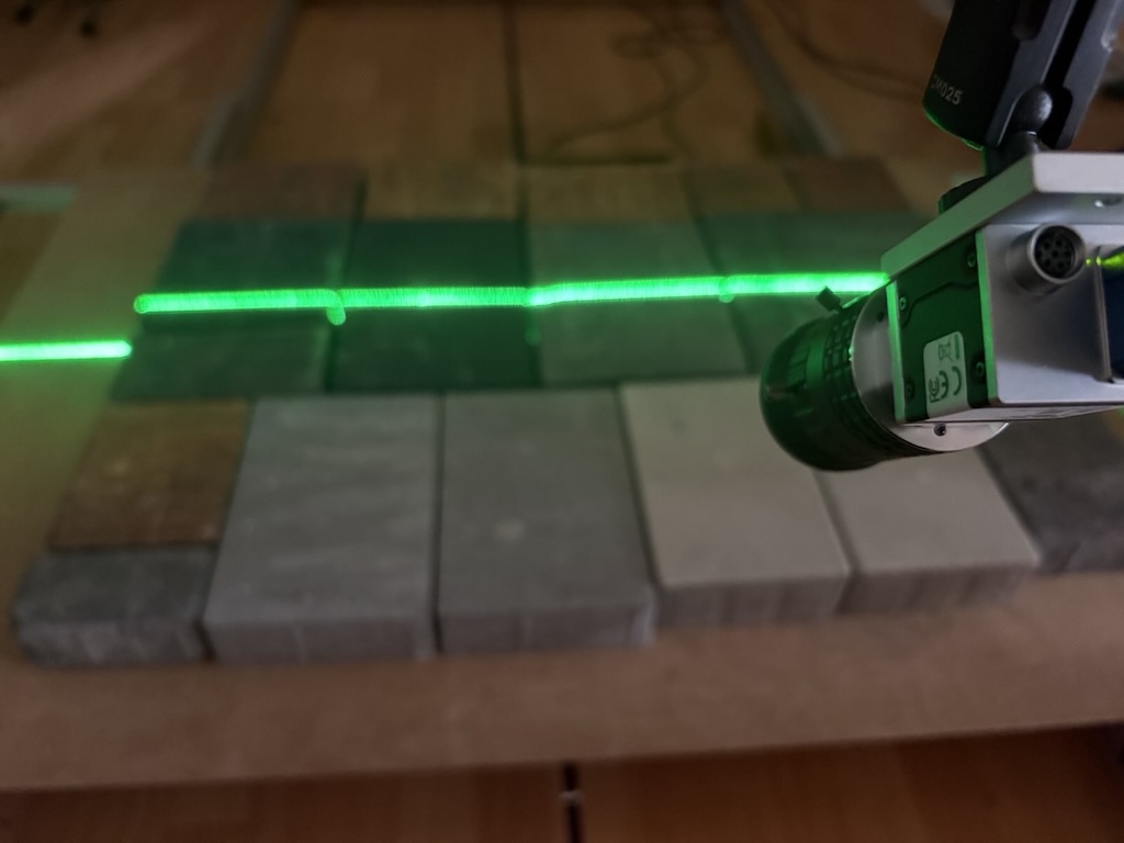
Building a reliable laser-based vision system — for example for 3D triangulation or surface profiling — is a classic engineering challenge. It is not simply buying components from a list; it is a system design exercise where every decision has consequences.
The key problem is that the parameters of the camera and laser are inseparably linked. A wrong choice at the start (e.g. an unsuitable camera sensor) can force costly and suboptimal compromises later (e.g. needing a dangerously powerful laser or a non-standard wavelength).
So how do you deal with this "chicken and egg" problem? What do you choose first? Let's analyze the key parameters and their interdependencies.
Key Component Parameters
Let's start by precisely defining the key parameters for each component.
1. Camera
- Sensor size and type: A key parameter determining sensitivity and field of view.
- Shutter type (Global vs. Rolling Shutter): A fundamental choice. Global Shutter is almost always required for inspecting moving objects on a production line to avoid distortion. Rolling Shutter is cheaper but suitable mainly for static objects.
- Resolution: Number of pixels (e.g. 1920×1080) defining the level of detail.
- Speed (FPS): Frames per second; must be synchronized with the production line speed.
- Mono vs. Color: For laser inspection, we almost always choose monochrome (mono) cameras. They have no Bayer filter (Color Filter Array), making them more sensitive to light — which is critical when capturing a faint laser line.
- Interface: E.g. GigE (Ethernet) for long distances and stability, or USB 3.x for high bandwidth at short distances.
- Built-in features: E.g. pre-processing, edge analytics.
2. Optics (Lens)
- Focal length (e.g. 12mm, 25mm): Defines the field of view (how "wide" the camera sees).
- Aperture range (F-stop, e.g. f/1.8–f/16): Controls how much light enters the sensor. Has a critical influence on depth of field.
- Maximum sensor size: The lens must be able to "cover" the entire camera sensor surface (e.g. 1/1.8" or 2/3").
- Distortion level: Important in precision measurements; often expressed as a percentage.
3. Laser
- Power (e.g. 5mW, 100mW): How "bright" the laser is.
- Wavelength (e.g. 520nm, 660nm): Defines the color (if visible) and, most importantly, how well the sensor "sees" it.
- Lens type: E.g. line-generating, cross, dot grid.
- Lens opening angle: Defines the length of the displayed laser line from a given distance.
Sensor Sensitivity vs. Laser Wavelength
This is the fundamental dependency that most often causes problems. In a system designed to detect anomalies in a laser line, that line must be clear and contrasty in the image.
One might think: "Just choose a powerful laser." This is a mistake.
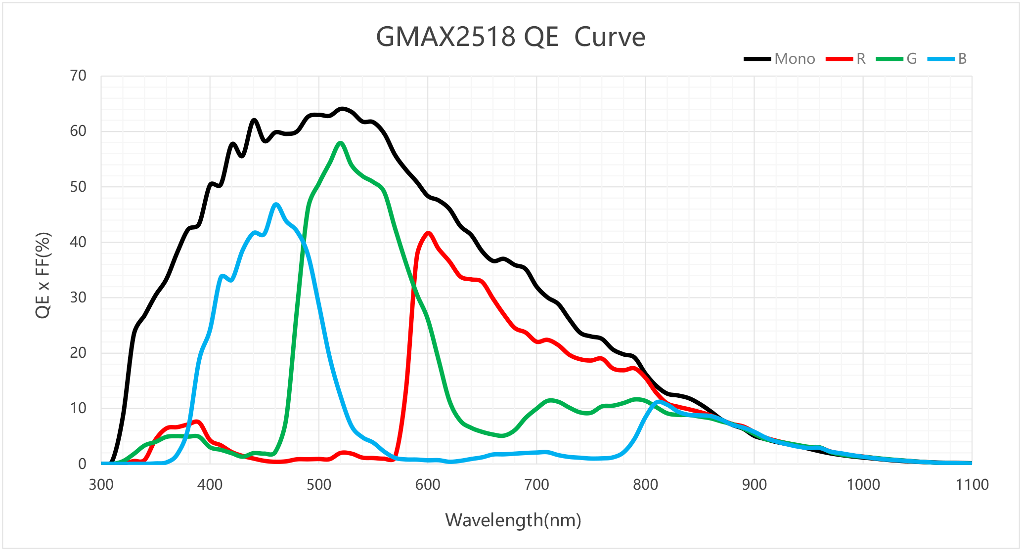
The truth is that every sensor has different sensitivity depending on the wavelength of light. This property is described by the Quantum Efficiency (QE) curve.
Let's look at an example QE curve for a popular mono sensor, such as the GMAX2518. As you can see, the sensitivity peak (highest QE coefficient) for this sensor falls at around 520 nm, which for the human eye is green.
What does this mean in practice?
- If we use a green laser (520nm), the sensor will use its maximum potential. We can get a bright image even at relatively low laser power.
- If, for safety or cost reasons, we choose a popular red laser (e.g. 638nm), the chart shows that sensor sensitivity at that point is lower. For this particular sensor, the difference in recorded brightness between green and red laser can exceed 20 percentage points.
- If we go further into the infrared (e.g. 850nm), sensitivity can drop dramatically, making the sensor nearly "blind" to that laser.
Conclusion: If we are limited in laser power (e.g. for operator safety reasons), we must select a laser with a wavelength close to the peak QE sensitivity of our sensor. Otherwise we will be fighting to extract signal from noise.
Aperture (F-stop) vs. Depth of Field
The second critical dependency concerns the lens. Aperture (F-stop) controls how much light enters the lens.
- Low F-stop value (e.g. f/2.0): The aperture is wide open. Lots of light enters. Great, right? The laser line is bright, we can shorten the exposure time.
- High F-stop value (e.g. f/8.0): The aperture is mostly closed. Very little light enters.
It might seem we always want the lowest F-stop to "collect" as much laser light as possible. Unfortunately, there are no free lunches in physics.
Opening the aperture (low F-stop) drastically reduces depth of field (DoF).
Why is this a problem? Imagine inspecting boxes on a production line. If we have a "paper-thin" depth of field (from an f/2.0 aperture), and a box bounces on the belt by a millimeter or is slightly tilted, the laser line on its surface will immediately fall out of focus. The image becomes blurry and problematic for CV algorithms.
On the other hand, closing down the aperture (e.g. to f/8.0) gives us a large depth of field. The system becomes robust to changes in object position — the laser line stays sharp. The price, however, is a dramatic drop in brightness. To compensate, we must either lengthen the exposure time (often impossible at high speeds) or significantly increase laser power.
And so we're back to square one.

Iterative Design
As you can see, selecting these components is a system of interconnected vessels.
- A fast production line forces a short exposure time.
- Short exposure time requires more light.
- More light can be obtained through a stronger laser or lower F-stop.
- Lower F-stop means less depth of field, which is risky.
- To maintain large depth of field (higher F-stop), we need an even stronger laser.
- Laser power is limited by budget, safety, and how well the sensor sees it (QE curve).
Unfortunately, this cannot be perfectly calculated in a spreadsheet. The biggest unknown is always the object itself. The way the laser line reflects from a surface — whether it's shiny mirror-like metal or porous matte plastic — fundamentally changes the appearance of the image.
That's why selecting these components relies heavily on the empirical method (trial and error).
In our case, when designing one of our recent systems, we took the following path:
- Defined the constraints: First we established the field of view and required precision, which allowed us to choose the camera (with appropriate resolution and shutter type) and lens.
- Laboratory testing: We then ordered a set of lasers with different powers and wavelengths for testing.
- Verification: We tested combinations on target material samples, looking for a compromise between line brightness, depth of field (adjusting F-stop) and exposure time.
This allowed us to select a laser that provided the best contrast and measurement stability at acceptable exposure parameters. (Big thanks to the team from Polish company Lambdawave (https://lambdawave.eu/) for their expert help and the opportunity to comprehensively test their products.)
In upcoming posts we'll cover the selection of each component and its parameters. Due to the scope and importance of this topic, each component will be described in a separate post.