Lens type and opening angle
The first decision concerns how the laser should project light onto the inspected surface. There are many options: a single point, a line, a cross, a dot grid — it all depends on the lens used.
In surface scanning systems we need a line laser that splits a single beam into a line. It is worth reaching for what is known as a Powell lens. It generates a line of uniform thickness and even intensity across the full width. The difference is clearly visible in Photo 1: on the left a line with a Powell lens, on the right — without it. Without Powell, the center of the line is noticeably thicker and brighter, while the edges are thinner and dimmer.
In our experience, using a Powell lens is one of those choices where you shouldn't cut corners — it directly translates into the quality of subsequent measurements.
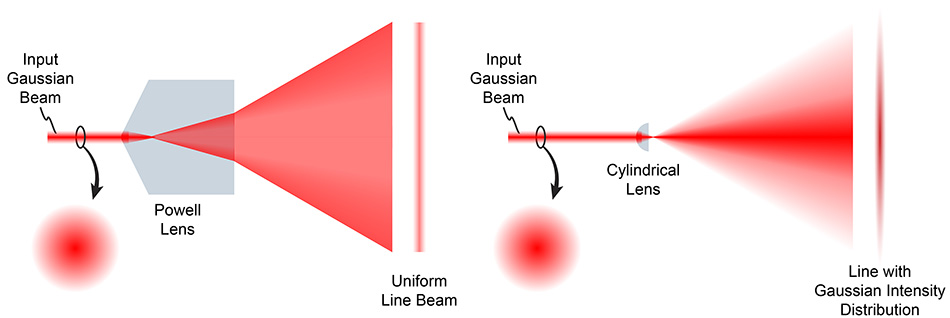
Photo 1: Comparison of laser line generated by a standard lens and a Powell lens
The second lens parameter is the opening angle. It works analogously to the focal length in a camera lens — it defines how far we need to move the laser from the illuminated object to cover it fully with light. In practice, the proven starting point is a 60° lens — a good compromise between working distance and line quality. If mounting space is severely limited, you can consider 90°, but you must accept that the line quality will be noticeably worse.
Wavelength
Wavelength is simply the color of light — values in nanometers (nm) directly translate into what the eye sees, as shown in Photo 2. Beyond the visible range there are also ultraviolet and infrared lasers, but to capture them we need specialized camera sensors — which are significantly more expensive than standard sensors designed for visible light.
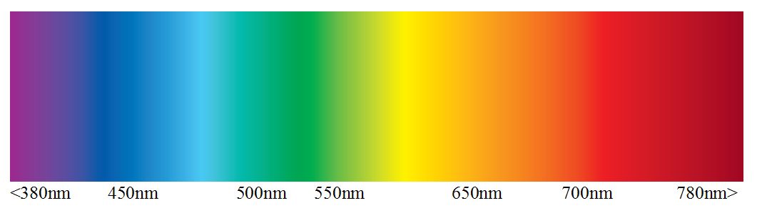
Photo 2: Wavelengths of visible radiation
That's why in our case we stayed in the visible spectrum. We made our final wavelength choice by overlaying the visible spectrum chart with the camera sensor sensitivity curve — we showed it in a previous post, but let's recall it here.
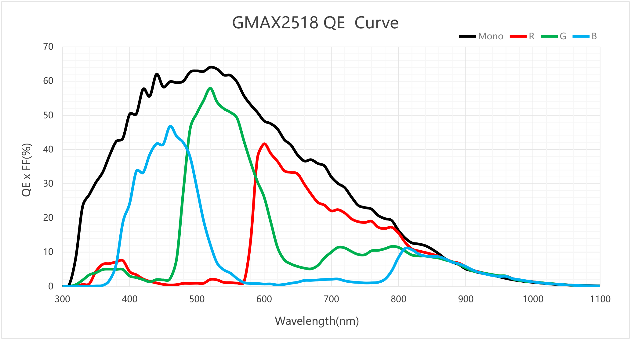
Photo 3: Sensor sensitivity curve by wavelength
As you can see, sensor sensitivity reaches its maximum at a wavelength of 520 nm, i.e. green — and that is exactly the laser we used in our system. An additional argument is that 520 nm performs well in various working conditions, so in our opinion it is the optimal choice.
Laser diode power
Laser power is usually given in milliwatts (mW) and not by accident — just 5 mW is enough to permanently damage human eyesight. Lasers above 1 W certainly exist and are sometimes necessary, but they require considerably greater care during operation.
Power selection is one of the more difficult decisions in the entire system, because it is affected by many variables, including:
- the width of the surface the laser line needs to cover,
- the lens aperture setting,
- the camera sensor size,
- the sensor exposure time,
- the distance between the camera and the laser line,
- external lighting conditions.
As you can see, there are many variables and it is difficult to calculate a "magic" power value in advance. In practice, trial and error works best — we start from a lower power and gradually increase it until we achieve satisfactory line quality.
It is worth keeping safety in mind throughout. The more powerful the laser, the greater the risk to people working nearby. For lasers above 1 W, the standard is to enclose them in a sealed, light-tight housing with no human access whatsoever. If the system is to operate where people have access to it, it is advisable to stay below 1 W.
What's next?
With this post we have closed out the three key components of a surface inspection vision system: camera, optics and laser. In upcoming posts we'll show how these elements come together into a working whole — we'll move on to building a laboratory test station and show how to construct your own production line for testing.