The Core Challenge: Defects Without a Shadow
The fundamental problem in a quality control system was detecting small holes on a flat surface. The key conditions that made this task exceptionally difficult were:
- Nature of the defect: The holes had the same color and texture as the base material, which ruled out simple color or pattern analysis.
- Ambient lighting: The production hall, with numerous roof and side skylights, was flooded with strong but extremely diffused light. This type of lighting is desirable for workplace safety, but for vision systems it is deadly — it practically eliminates all shadows.
Without shadows, depressions become optically "flat" and impossible to distinguish from the rest of the surface.
The First Approach and Its Failure: A Standard Industrial Camera
The first hypothesis was to use a standard high-resolution industrial camera pointed at the production line.
Result: Complete failure. The image captured by the camera showed no trace of defects.
Failure analysis: The problem was not in the camera's resolution, but in the physics of lighting. The absence of shadows in the image meant an absence of depth information. The conclusion was clear: we need to take control of the lighting and actively generate shadows.
Evaluating Alternative Lighting Architectures
Three competing lighting strategies were considered:
Approach #1: Linear Illuminator Positioned in Parallel
- Concept: Use a single long linear lamp, positioned at an angle along the production line.
- Problem: Non-uniform illumination. Light intensity drops dramatically with distance.
Verdict: Rejected.
Approach #2: Line Scanning with an LED Lamp
- Concept: Change the architecture to "line by line." A linear lamp is positioned perpendicular to product movement. A line-scan camera is used for acquisition.
- Advantages: Solves the illumination uniformity problem.
- Disadvantages:
- Mechanical complexity — requires an active lamp positioning system
- High power consumption
Verdict: Technically feasible, but complex and expensive to operate.
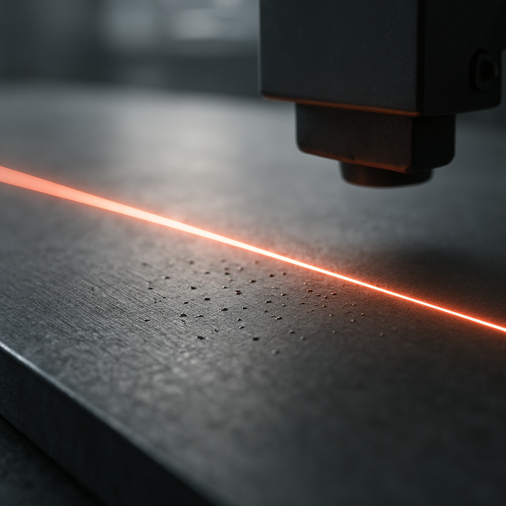
Approach #3: Line Scanning with a Laser
- Concept: Identical architecture to approach #2, but the light source is a line laser.
- Advantages:
- No moving parts — the laser can be placed at a large distance
- Extremely low power consumption
Verdict: Winner.
Decision and Next Steps
The laser scanning approach was selected because it offers the most reliable and cost-effective architecture. Eliminating moving parts directly translates into a lower total machine cost and higher operational availability.
Upcoming posts in the series will dive into the implementation details:
- Selecting laser parameters
- Analyzing the laser line signature on defects
- Image processing strategies and algorithm development